LEGO SPIKE Gesture-Controlled 3DOF Robotic Arm
1. Learning Objectives
1. Knowledge Objectives
- Understand the basic principles of AI vision gesture recognition
- Learn the meaning of X/Y coordinates from a detected hand box
- Learn LEGO SPIKE motor angle control
- Understand communication protocol parsing
- Understand the difference between Position Control and PID Control
2. Skill Objectives
- Build a 3DOF robotic arm
- Control the robotic arm using hand gestures
- Program AI vision logic in RobotCode App
- Program motor control in SPIKE App
- Debug gesture-to-motion mapping
3. Thinking Objectives
- Develop system thinking: Gesture → Vision → Data → Robot Motion
- Understand human-machine interaction
- Experience AI + Robotics integration
2. Teaching Preparation
1. Hardware Preparation
| Hardware | Quantity | Description |
|---|---|---|
| LEGO SPIKE Hub | 1 | Main controller |
| AI Vision Sensor | 1 | Connected to Port A |
| LEGO Motors | 3 | Connected to Ports C, D, E |
| USB Cable | 1 | Program downloading |
| Computer/Tablet | 1 | Programming device |
2. Port Connection
| Device | Port |
|---|---|
| AI Vision Sensor | Port A |
| Left/Right Rotation Motor | Port C |
| Up/Down Motor | Port D |
| Gripper Motor | Port E |
3. Software Preparation
| Software | Purpose |
|---|---|
| LEGO SPIKE App | Motor control |
| RobotCode App | AI vision and protocol processing |
3. Teaching Process
Stage 1: Introduction
Teacher Demonstration
Teacher demonstrates:
- Move hand left → Arm rotates left
- Move hand right → Arm rotates right
- Raise hand → Arm lifts up
- Close fingers → Gripper grabs object
Ask students:
“How can the robotic arm understand our gestures?”
Stage 2: Robotic Arm Building
Structure Requirements
The robotic arm should include:
- Left/right rotation freedom (Motor C)
- Up/down lifting freedom (Motor D)
- Grabbing freedom (Motor E)
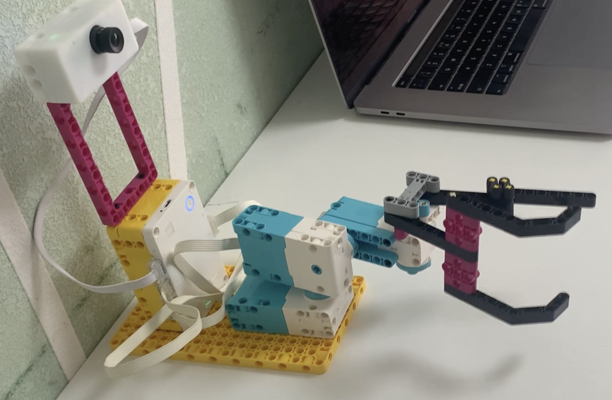 The simple crawling structure can be referenced from the official setup version, or you can build your own.
Structure Suggestions
Motor C
Controls left/right rotation.
Motor D
Controls arm lifting movement.
Motor E
Controls grabbing and releasing.
Stage 3: Beginner Programming (Position Control)
Teaching Focus
At the beginner stage:
No PID algorithm is used
Use direct position control
Focus on:
- Coordinate detection
- Protocol design
- Motor mapping
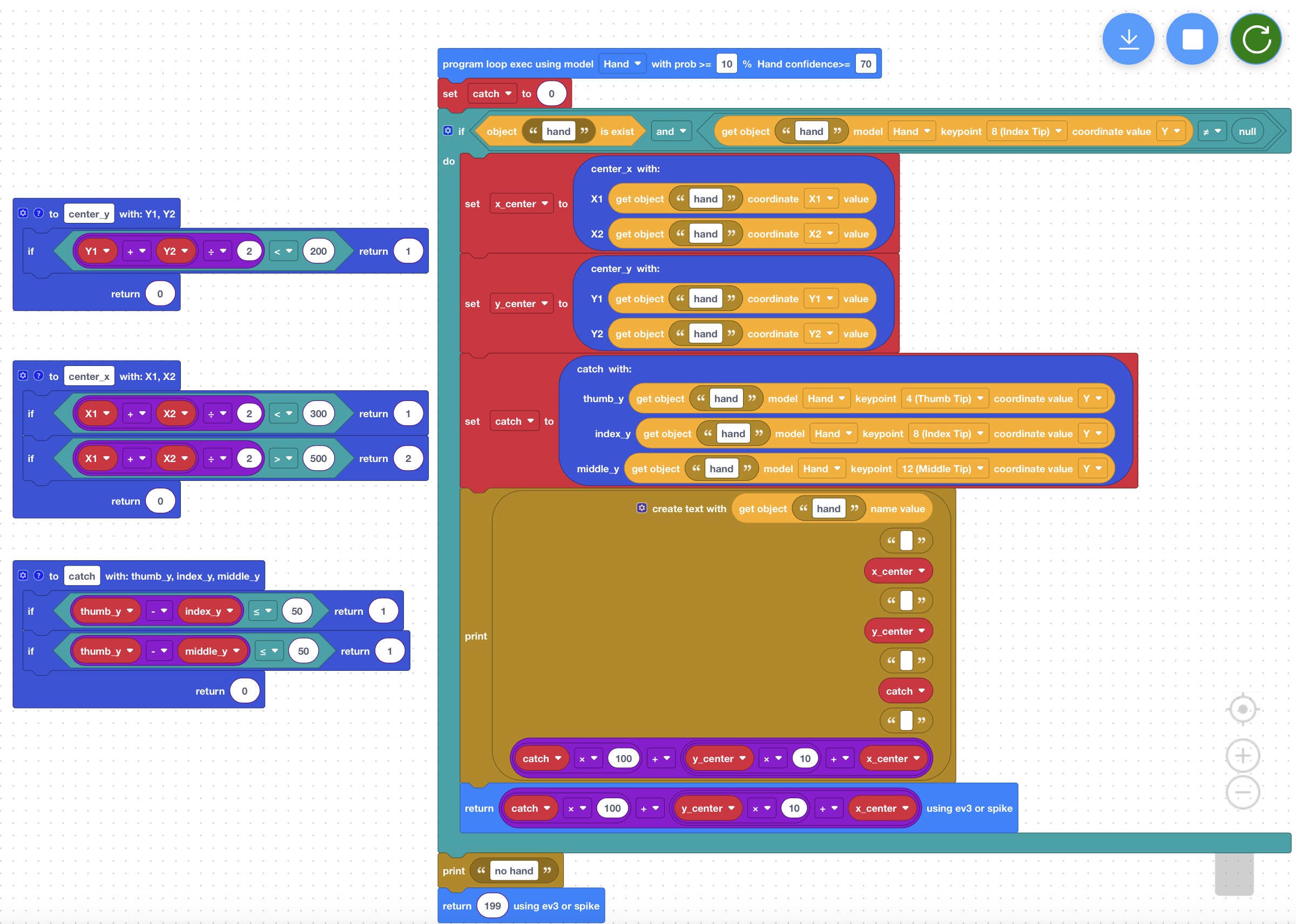
RobotCode App Logic
1. Camera Resolution
Set camera resolution width to:
800 pixels
2. Left/Right Logic (Motor C)
| X Coordinate | Motor C Angle |
|---|---|
| X < 300 | 320° (Left) |
| 300 ~ 500 | 0° (Center) |
| X > 500 | 40° (Right) |
3. Up/Down Logic (Motor D)
| Y Coordinate | Motor D Angle |
|---|---|
| Y < 200 | 45° (Up) |
| Y ≥ 200 | 0° (Down) |
4. Grab Detection Logic (Motor E)
Detect:
The Y-distance between:
- Thumb fingertip
- Index fingertip
When:
Distance ≤ 50
The system considers it as: “Fingers closed together”.
The gripper performs a grab action.
Protocol Design
Protocol Structure
Use:
Hundreds + Tens + Ones
Protocol Meaning
| Digit | Meaning |
|---|---|
| Hundreds | Grab action |
| Tens | Motor D state |
| Ones | Motor C state |
Protocol Definitions
Hundreds Digit (Grab)
| Value | Meaning |
|---|---|
| 0 | Release |
| 1 | Grab |
Tens Digit (Up/Down)
| Value | Meaning |
|---|---|
| 0 | Down position |
| 1 | Up position |
Ones Digit (Left/Right)
| Value | Meaning |
|---|---|
| 0 | Center |
| 1 | Left |
| 2 | Right |
Protocol Example
101
Means:
- Grab action
- Motor D at down position
- Motor C at left position
Senrayvar APP code
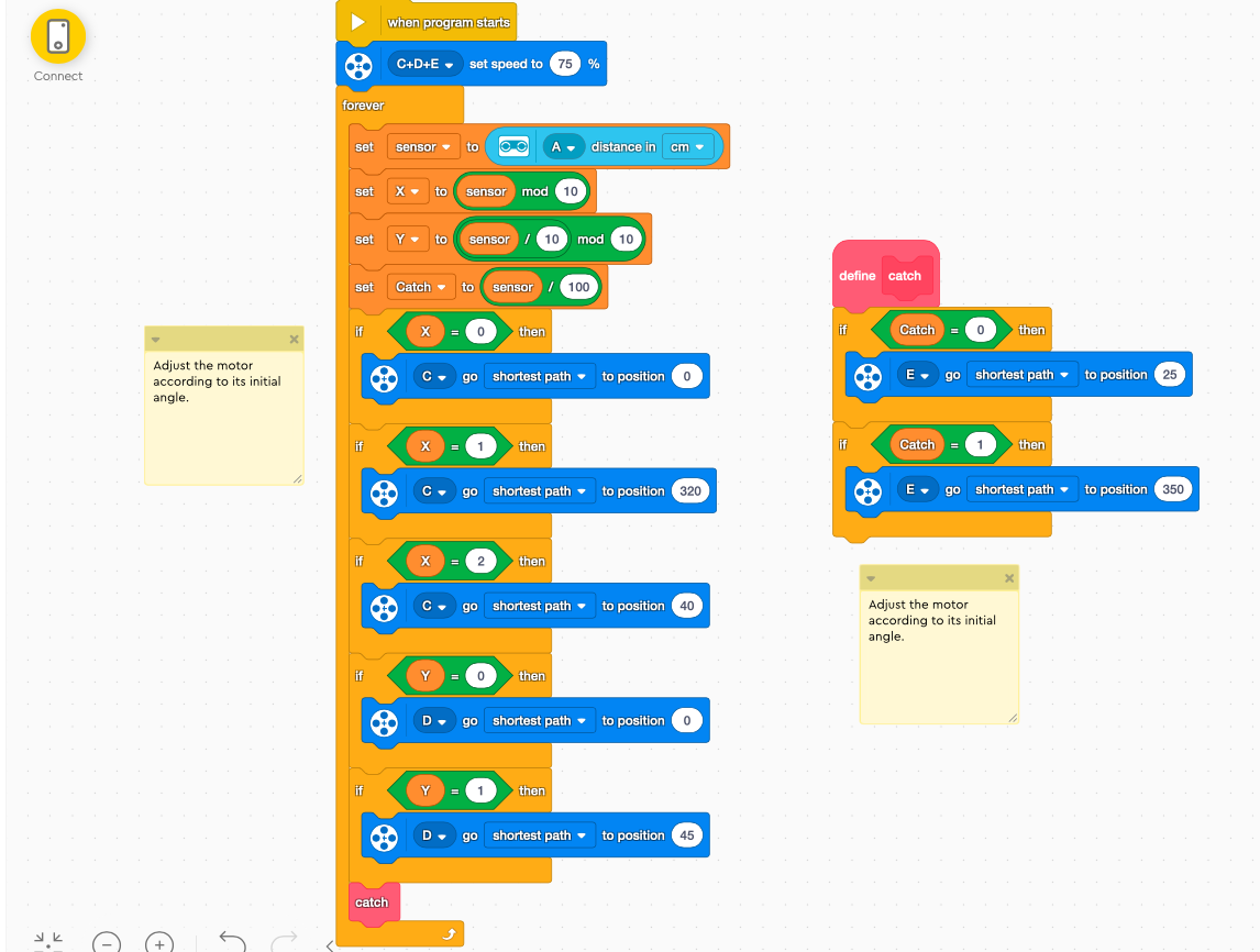
SPIKE App Logic
Protocol Parsing Example
Example: 101
Parsed result:
- Hundreds digit = 1 → Grab
- Tens digit = 0 → Down
- Ones digit = 1 → Left
Motor Control Mapping
Motor C
| State | Angle |
|---|---|
| 0 | 0° |
| 1 | 320° |
| 2 | 40° |
Motor D
| State | Angle |
|---|---|
| 0 | 0° |
| 1 | 45° |
Motor E
| State | Action |
|---|---|
| 0 | Release |
| 1 | Grab |
code demo
Stage 4: Advanced Programming (P-Control)
Teaching Focus
The advanced stage introduces:
- Smooth control
- Proportional control (P-Control)
- Deadzone control
- Shortest-path rotation
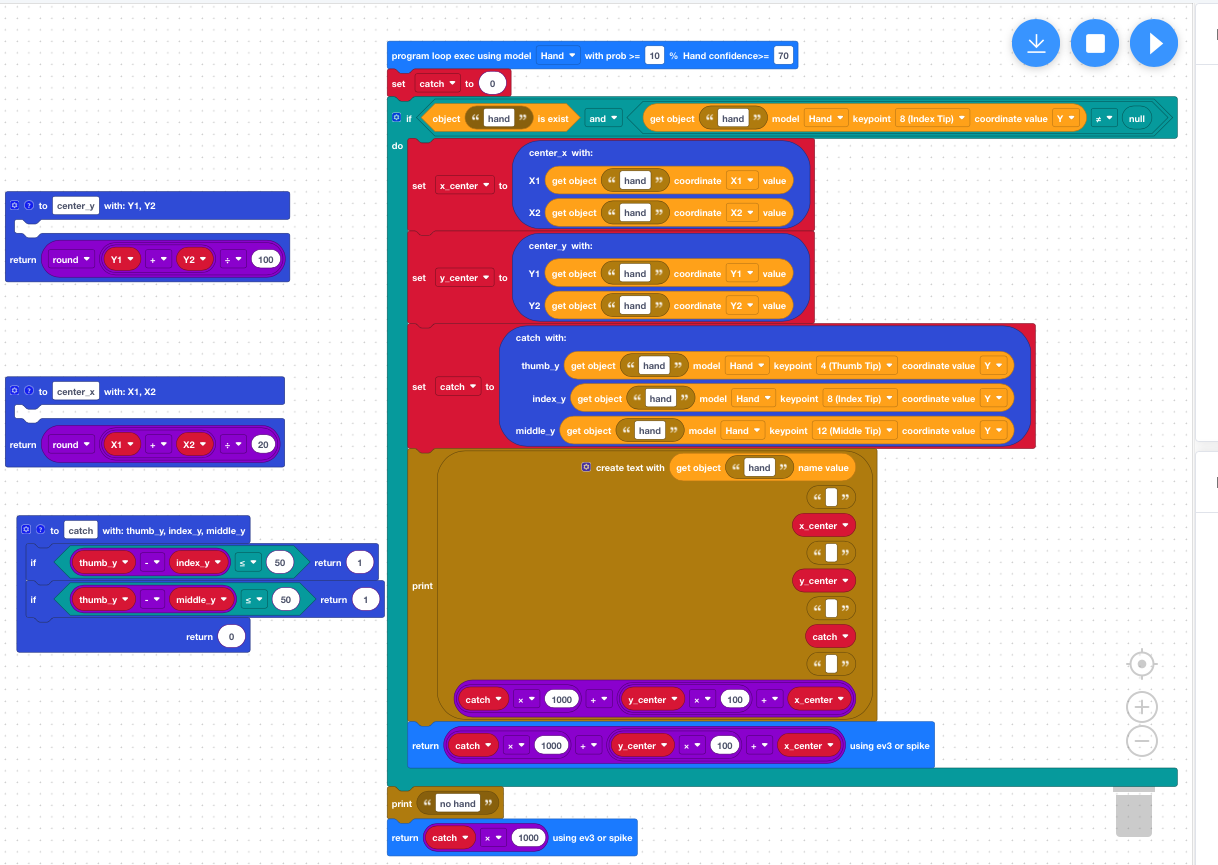
Advanced Protocol Design
RobotCode App returns:
- x = Rectangle center X / 10
- y = Rectangle center Y / 50
- catch = 0 or 1
Protocol Formula
catch * 1000 + y * 100 + x
Example
1642
Means:
- Grab action
- y = 6
- x = 42
senrayvar scratch 代码
Advanced SPIKE Python Example
import distance_sensor
import motor
import runloop
from hub import port
# from app import display

# --- Core Configuration Parameters ---
GRAB_DEGREE = 350
RELEASE_DEGREE = 25
MOTOR_SPEED = 200

X_CENTER = 40  # Mapped center point for X-axis
Y_CENTER = 6   # Mapped center point for Y-axis, no need to move downward

X_MULTIPLIER = 2
Y_MULTIPLIER = 5

# --- Smooth Control Parameters (P-Control) ---
GAIN = 6        # Speed gain (sensitivity). Increase it (e.g., 8) if the motor responds too slowly. Decrease it (e.g., 4) if it overshoots and wobbles.
MAX_SPEED = 400 # Limits the maximum rotation speed to prevent overly violent movements
DEADZONE_C = 2  # Deadzone (degrees): If the error is within this range, it's considered arrived. The motor brakes to prevent buzzing from tiny fluctuations.
DEADZONE_D = 2

def get_shortest_error(target, current):
    """Calculate the shortest path angular error (-180 to 180 degrees)"""
    error = target - current
    if error > 180:
        error -= 360
    elif error < -180:
        error += 360
    return error

async def main():
    while True:
        dist_mm = distance_sensor.distance(port.A)

        if dist_mm <= 0:
            # When the target is lost, let the motor coast smoothly to a stop instead of braking hard
            motor.stop(port.C, stop=motor.COAST)
            motor.stop(port.D, stop=motor.HOLD)
            await runloop.sleep_ms(20)
            continue

        dist_cm = dist_mm // 10

        # Parse data
        x_val = dist_cm % 100
        y_val = (dist_cm // 100) % 10
        action_code = dist_cm // 1000

        # Calculate the new theoretical target positions (within 0-359 range)
        target_c = int((x_val - X_CENTER) * X_MULTIPLIER) % 360
        target_d = int(-(y_val - Y_CENTER) * Y_MULTIPLIER)

        # Get the actual current absolute angle of the motor
        current_c = motor.absolute_position(port.C) % 360

        # Calculate the direction and amount of rotation needed (shortest path)
        error_c = get_shortest_error(target_c, current_c)

        # display.text(str(target_c) + " " +str(target_d) + " " + str(action_code))

        # ----------------------------------------------------
        # Core Modification: Use proportional speed control instead of position control
        # ----------------------------------------------------

        # Control Motor C (X-axis)
        if abs(error_c) > DEADZONE_C:
            # The further the distance, the higher the calculated speed; it automatically slows down when close
            speed_c = int(error_c * GAIN)
            # Constrain speed within MAX_SPEED range
            speed_c = max(min(speed_c, MAX_SPEED), -MAX_SPEED)
            # Use motor.run to send continuous speed commands
            motor.run(port.C, speed_c)
        else:
            motor.stop(port.C, stop=motor.COAST)

        # Control Motor D (Y-axis)
        if target_d > 5:
            motor.run_to_absolute_position(port.D, 45, MOTOR_SPEED, direction=motor.SHORTEST_PATH)
        else:
            motor.run_to_absolute_position(port.D, 0, MOTOR_SPEED, direction=motor.SHORTEST_PATH)

        # Control Grabber Motor E (grabbing and releasing are fixed-point actions, so position control works fine)
        if action_code == 1:
            motor.run_to_absolute_position(port.E, GRAB_DEGREE, 1000, direction=motor.SHORTEST_PATH)
        elif action_code == 0:
            motor.run_to_absolute_position(port.E, RELEASE_DEGREE, 1000, direction=motor.SHORTEST_PATH)

        # Refresh interval is set to 10ms. 5ms is too fast for physical motor response and can cause command backlogs. 20ms (~50fps) is smooth enough visually.
        await runloop.sleep_ms(10)


runloop.run(main())
Advanced Stage Core Idea
Why is advanced control smoother?
Because:
Farther target → Faster movement Closer target → Slower movement
This prevents sudden stopping.
Why use a deadzone?
Vision tracking may slightly shake.
Without a deadzone:
- Motors constantly adjust
- Motors may overheat
- Buzzing noise may occur
4. Demonstration and Testing
Test Items
1. Left/Right Tracking Test
Move the hand:
- Check whether the robotic arm follows correctly.
2. Up/Down Control Test
Raise the hand:
- Check whether the robotic arm lifts correctly.
3. Grab Test
Close fingers together:
- Check whether the gripper grabs correctly.
4. Full Motion Test
Perform continuously:
- Left movement
- Right movement
- Up/down movement
- Grab action
Observe system stability.
5. Extension Thinking
Question 1
How can we make the robotic arm smoother?
Besides P-Control, what other algorithms can be added?
Hint:
- PID control
Question 2
What additional gestures can AI recognize?
Examples:
- OK sign
- Thumbs up
- Fist
- Number gestures
Question 3
What can a robotic arm with more DOF do?
Examples:
- Object sorting
- Writing
- Carrying objects
- AI assistant functions
6. Teaching Summary
Students learned:
- AI vision recognition
- Gesture coordinate acquisition
- Data protocol design
- LEGO SPIKE motor control
- 3DOF robotic arm control
Students experienced:
“Controlling robots using hand gestures”.
7. Classroom Presentation
Presentation Tasks
Each student group should:
- Demonstrate gesture-controlled robotic arm movement
- Complete a grabbing task
- Present creative extensions